
This document has been prepared in order to be used by OSAI. It describes the latest release of the product. OSAI reserves the right to modify and improve the product described by this document at any time and without prior notice. Actual application of this product is up to the user. In no event will OSAI be responsible or liable for indirect or consequential damages that may result from installation or use of the equipment described in this text.


Added a new paragraph “Routines activated by Fast Input Events” Changed picture (added Fast Input) Added “Attention” Changed picture (added Fast Input) Added description EventTaskFIN
Added description in the tableChanged picture Added description in the table Added “Attention” Changed picture Added “Attention” Added a new paragraph “ MANAGEMENT of SHARED SPINDLE RACK (GTS)” Added a new paragraph “ Added a new paragraph “ MIGRATION OF AXES (GTA) MANAGEMENT RACK”
Changed description Changed table Changed table Added description in the table Changed table and description Added a new paragraph “Shutdown Warnings” Added a new paragraph “Mechatrolink Emergencies”
PROGRAM ACTIVATION (SPG) MANAGEMENT RACK” Chapter 10 Chapter 12 APPENDIX B 10 Series CNC WINPLUS Application Manual (04) Added new paragraphs “Coordinated Axes” Point-Point Axes” “Gantry Axis” Added description in the table Added a new appendix “ HILSCHER CANOPEN ERROR CODES”

The 10 Series numerical control introduces many new Technical concepts. One of the most important of these concepts is the concept of information exchange between the CNC and the integrated PLC (Programmable Logic Controller).
Conventional controls use a window with a large amount of fixed flags, which are continuously scanned and updated by both CNC and programmable logic control.
The concept of 10 Series by-passes this general conception with a simple but unique solution: both CNC and PLC use function calls to alert each other, to pass information or to request a certain action. These function calls need only be executed on event, thus freeing up CPU capacity and increasing the general system performance.
This manual explains the new concept and shows how applications can use its power. ABOUT THIS MANUALThis manual is intended to be used by the OEM personnel in charge of the programming of the machine tool interface. It gives an overview of the software architecture to be used to develop the programmable logic.
• it does NOT explain the WinPLUS programming language and the use of any of its language elements. 10 Series CNC WinPLUS Application Manual (04) 1
module: it shows the timing and the execution priorities of the different routines on the I/O processor and it makes you familiar with the special execution mode of the background logic programs. Finally, it gives a list of declarations needed to define the different routines.
Chapter 3 deals with the data areas in the PLC module's memory and in its dual port. Chapter 4 explains the configuration of the interface between part program and logic. Chapter 5 explains the functions of the interface between the part program and the logic. Chapter 6 explains the configuration and the use of filters of executive commands. Chapter 7 explains the configuration of the emergency routines and of OEM softkeys. Chapter 8 describes management of emergencies. Chapter 9 describes OEM softkey management. Chapter 10 this is the practical part of the manual which explains how to use the communication concepts of the controls to create efficient applications. Chapter 11 this chapter describes how to use the INTERBUS feature on 10 Series systems. Chapter 12 this chapter describes how to use the CANOPEN feature on 10 Series systems. Chapter 13 this chapter describes how to use the OSWIRE feature on 10 Series systems. Chapter 14 Describes how to use the PROFIBUS function in Series 10 systems Appendix A contains a glossary of verbs and expressions used in this manual. Appendix B contains HILSCHER CANOPEN ERROR CODES OTHER MANUALS ABOUT WINPLUS Beside this manual there are 2 other specific manuals on WinPLUS: • 10 Series CNC WinPLUS LIBRARY code : 45006867F This manual covers the library function calls and the function blocks available in the WinPLUS programming language: − System function calls − function calls • 10 Series CNC WinPLUS development tool code 4500 6672 P This manual describes the WinPLUS development tool, the editors and the utilities to generate an executable logic program: − ladder diagram / function block diagram editor ( FBD/LD ) − sequential function chart editor ( SFC ) 2 10 Series CNC WinPLUS Application Manual (04)
For correct control operation, it is important to follow the information given in this manual. Take particular care with topics bearing one of the signs: WARNING, CAUTION or IMPORTANT, which indicate the following types of information:
Draws attention to facts or circumstances that may cause damage to the control, to the machine or to operators.
Indicates information to be followed in order to avoid damage to equipment inIndicates information that must be followed carefully in order to ensure full success of the application.
10 Series CNC PLUS Application Manual (04) 3


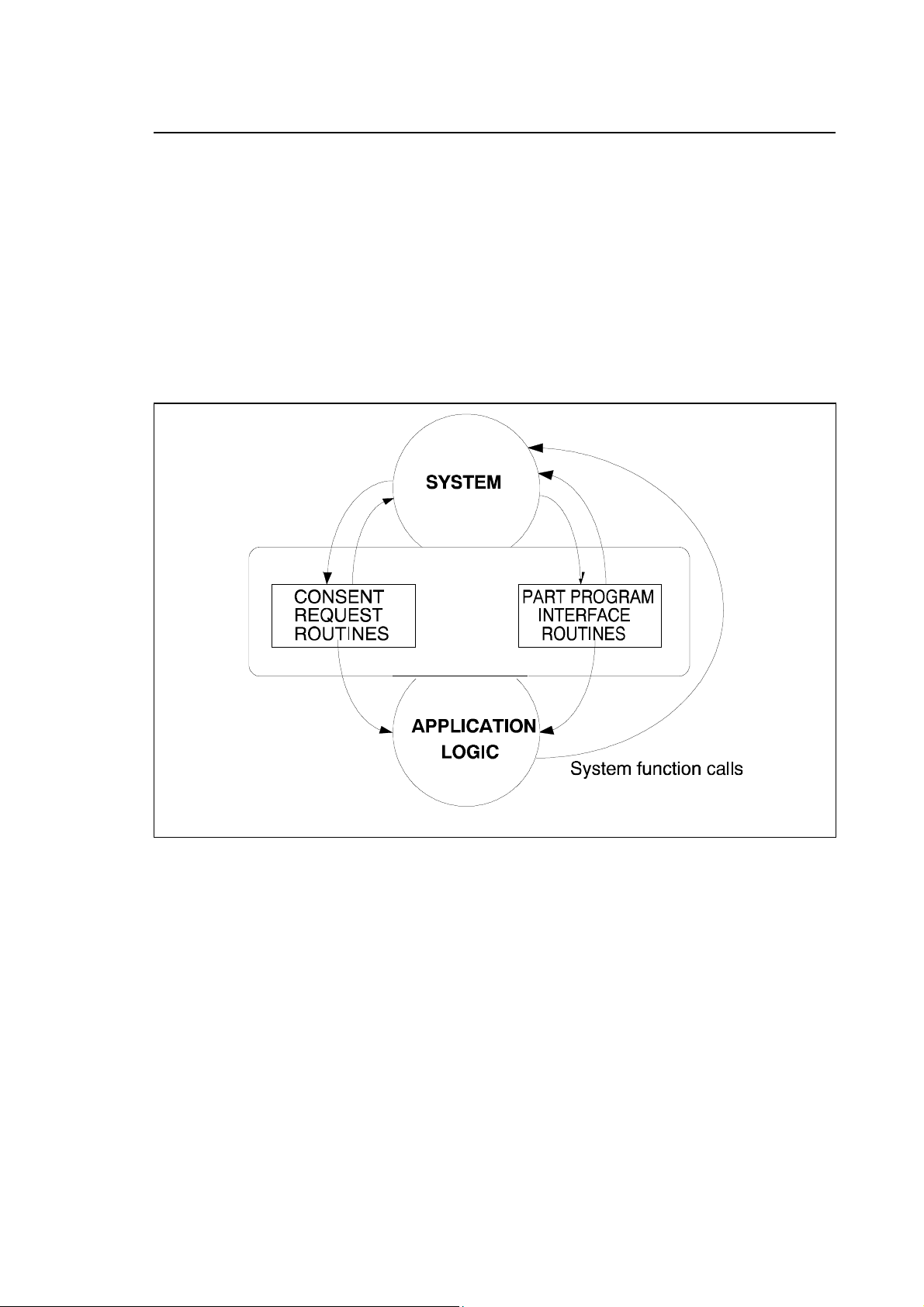
The system communicates with the logic through a logic interface. This interface is a data buffer in which the system writes the data to send to the machine logic program.
The data buffer is divided according to its functions in different parts called RACKS. They are always active. 10 Series CNC WinPLUS Application Manual (00) 1-1
The logic from its part communicates with the system through a set of function calls which can include a parameter exchange between the two parties. There are two types of function calls:
• NO WAIT functions pass a command (with parameters) to the system without waiting for an answer (the application program execution is not suspended).
• WAIT functions pass a command to the system and wait for a response ( the logic execution is suspended until the response arrives)
The third communication channel between the logic and the system are the common data areas in the battery buffered dual ported memory of the I/O processor board. These areas can be divided in:
• System area . This is a group of 500 variables of the type short (16 bit integer word) containing the status of the system and/or the processes.
• Global variables . These variables are referred to as "G" variables. They have two formats; short and double (precision floating point). They can be read and written by both part program and logic program. The G variables are retentive, i.e. they are not cleared after powering up the system.
• Tables . Tables are retentive memory areas in the dual port of the I/O processor module. They can be commonly accessed by the system and by the logic programs. The data contained in tables includes:
− tool offset data − axes origin data − axes offsets END OF CHAPTER 1-2 10 Series CNC WinPLUS Application Manual (00)
The logic program is organised in independent routines. All these routines run on the I/O processor module and have different priorities depending on their use.
The various routines are activated by the operating system of the PLC following specific events, or at given times, or may also be run continuously (in loops).
AVAILABLE ROUTINES Routines activated on time (foreground)This routine (only one can be present) will be executed on each clock tick of the I/O processor module. This clock tick is currently set at 10 ms. If the foreground routine execution time exceeds the available time (max. 10 ms), the system will generate an "overrun error" and go into emergency status. The routine must have the shortest execution time possible ( < 5 ms) because the remaining TICK time is used by routines with a lower priority. The primary use of the foreground routine is to "latch" events to be executed with fast, precise timing such as read/write physical I/O device status or handling of security/emergency devices. Requested name for the routine : fore.
Continuously executed routines (background routines)A background routine executes continuously in a loop like a program in a standard PLC. The I/O processor can run up to 12 background routines in parallel.
Each background routine can execute functions of the WAIT type, which will suspend the execution of that background routine until arrival of the response. In the meantime the other background routines will continue executing. In reality, when one routine is suspended, control passes to the next one.
The logic programmer has to optimise the performance of the I/O processor by distributing the logic in the available background routines. Requested name for the routine : back1 …back12.
10 Series CNC WinPLUS Application Manual (04) 2-1
This routine can be recalled whenever an emergency condition occurs. It can be activated only if it has been loaded. In an emergency, the logic application may have to execute logic sequences in parallel with the actions performed by the system. Mandatory name for the routine:
EventTaskEmg. Routine activated by pressing a softkey (OEM softkey routine)This routine is called whenever an OEM softkey is pressed (or released).It can be activated only if it has been loaded.
The OEM softkeys are defined in AMP, enabling the OEM to provide its application with the same appearance and operability as are typical of the standard system (AMP configuration manual). The management routine of an OEM softkey works at a very low priority level. Mandatory name for this routine: EventTaskHum .
Routines activated by part program events (part program interface)Specific routines (one for each process configured) are called whenever a part program block contains functions relating to the logic (e.g., M codes, S and T functions, and all the other functions that can be grouped under the heading of ancillary logic functions). These routines can be activated only if they have been loaded. Mandatory name for these routines: EventTaskPPX, where X stands for the name of the associated process.
Routines activated from the console (request for enable signal)Specific routines (one for each process configured) are called whenever a command is imparted to the system (e.g., cycle start, reset, etc.), enabling the logic to read and/or suspend the commands imparted to the system by the operator. These routines can be activated only if they have been loaded.
These routines are provided for most of the commands that can be entered via softkeys and/or from the MTB panel. Mandatory name for these routines: EventTaskConX, where X stands for the name of the associated process.
Routines activated when requested by the logicSpecific routines (from 1 to 39) will be called whenever the logic notifies an event through the SetEventTask function. Once activated, these tasks will be completed through the end.
Mandatory name for these routines: EventTaskLogX , where X stands for the task number. 2-2 10 Series CNC WinPLUS - Application Manual (04)
This routine will be activated only if it has been loaded. The application logic understands what Fast Input has been executed. To understand which input has been executed refer to the following table.
0 Fast Input#1 1 Fast Input#2 2 Fast Input#3 3 Fast Input#4 4-15 Reserved If two Fast Input events occur at the same time, the routine will be called twice. Mandatory name for the routine: EventTaskFIN.The data supplied from CNC to the logic is written in RACK M every time that the data is memorised in the interface buffer interrupting the execution of the Background routine for the necessary time that it takes to be written.
The background routines can be synchronised with a set of semaphores (32) with the WAIT and SEND instructions. With the WAIT instruction and a semaphore number (from 0 to 31) it is possible to suspend the execution of a routine (task) until one of the other routines executes the SEND instruction with the same semaphore number . In this way it is possible to synchronise the execution of a task with another event in another task.
10 Series CNC WinPLUS - Application Manual (04) 2-3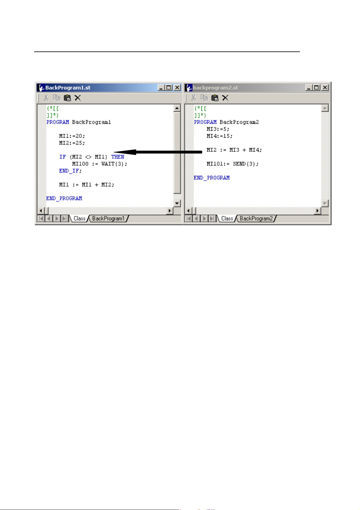
The instruction WAIT (3) suspends the execution of the BackProgram1 task until the command SEND (3) in the BackProgram2 task executes. Naturally the exact point (in time) of task resume depends on its priority.
2-4 10 Series CNC WinPLUS - Application Manual (04)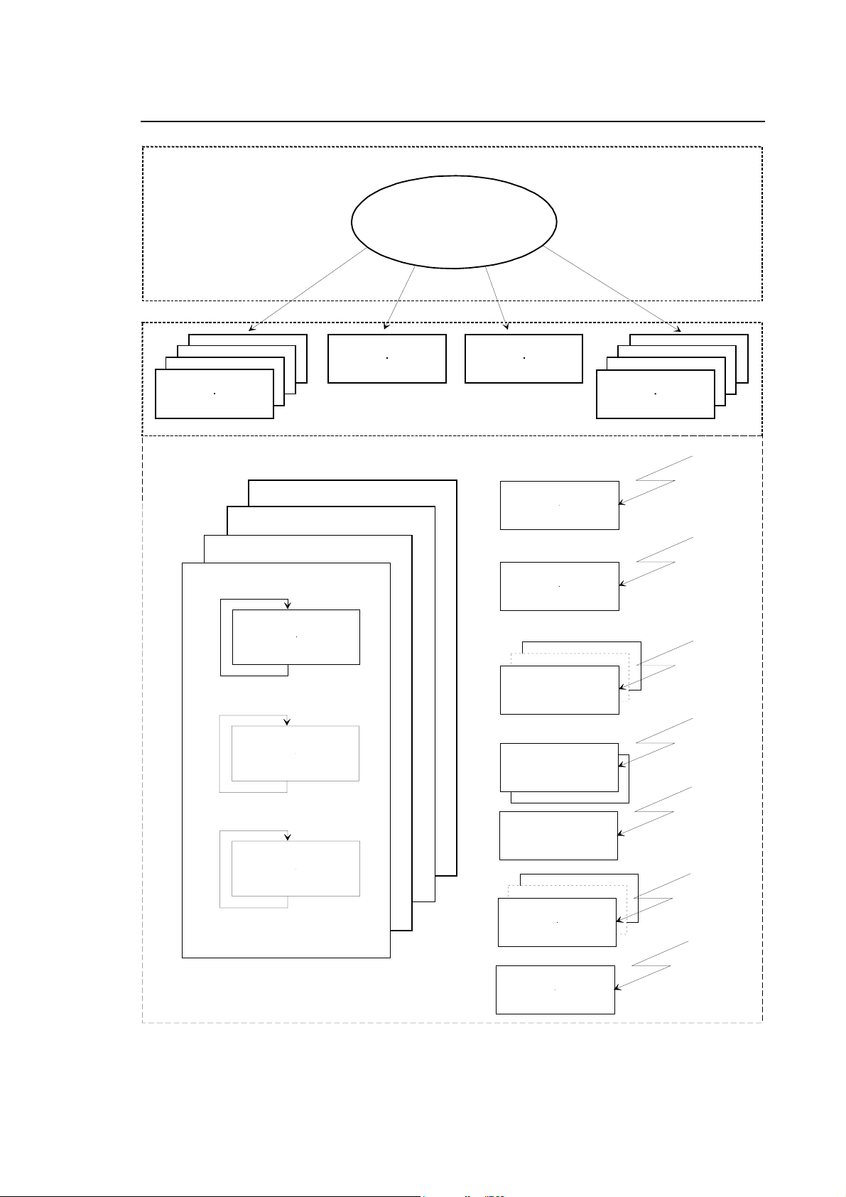

If a SEND on a semaphore is issued without a task waiting for this semaphore. The SEND instruction will be ignored. Any routine in WAIT status can only be released by the equivalent SEND instruction. The routine containing the SEND instruction must be synchronised with the routine containing the WAIT status request.
You are not allowed to use the WAIT/DLY instructions in foreground, fast input and emergency routines
The use of the SEND and WAIT functions for synchronisation can produce some inhibits to the system if used during the management of the Part Program functions:
RQP RQT TOU GTA GTSThe problem can happen if the task that performs the SEND to the routines managing the functions in the list above also performs process applications (for example NC functions for position or status acquisition).
If they are wanted to use criterions of synchronism founded on WAIT and SEND it it is necessary to make sure that the task that sends the SEND doesn't perform any application toward the NC process. It is suggested that an ad hoc task is created that verifies the conditions of acceptance of the applications (e.g. possibility to use the in demand axes through GTA) and you effect the SEND to unhook the task applicant.
2-6 10 Series CNC WinPLUS - Application Manual (04)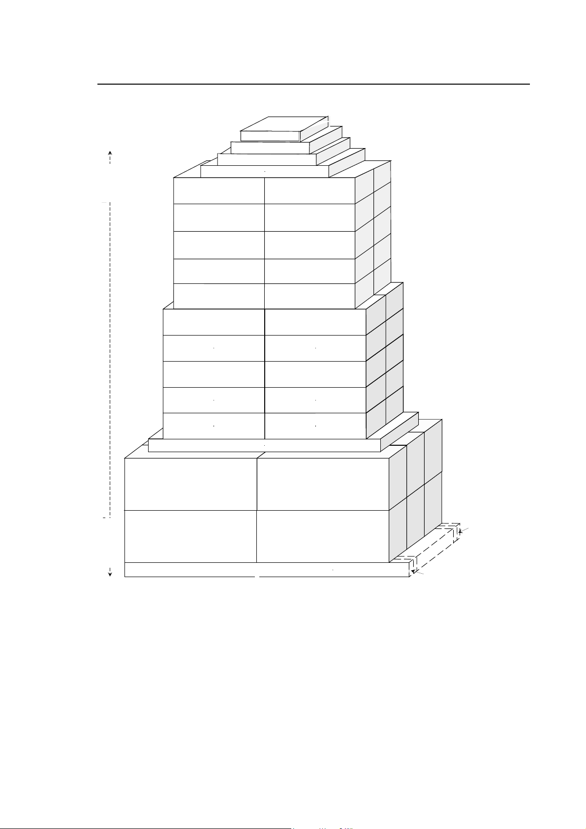
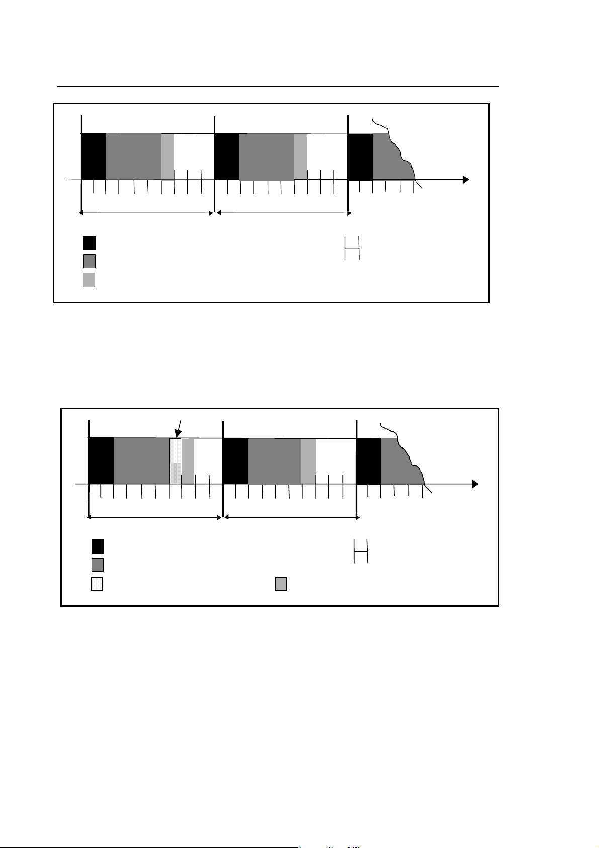
Every 10 ms the system updates the I/O, executes all the foreground routine and executes a background in 1 ms. Every 10 ms one of the background routines will be executed in sequence. If a background routine lasts for less than 1 ms, it will be executed again from the start, until the time runs out. No routine will be interrupted.
Part Program interface routine foreground High priority routine Fig. 2-4 High Priority Interrupt Operation routine background 2-8 10 Series CNC WinPLUS - Application Manual (04)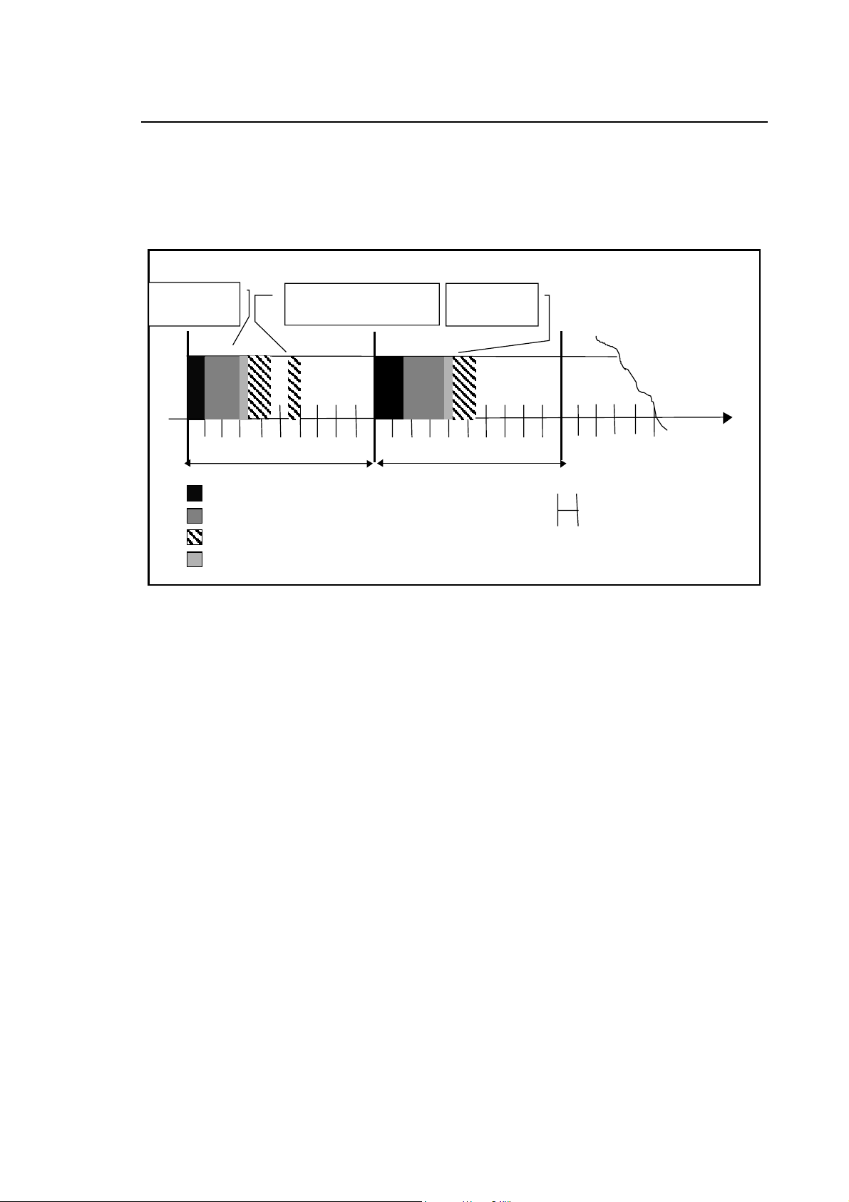
When emergencies occur, the continuous operation of the I/O processor will be interrupted and the high priority routines required will be executed immediately. Note that the continuous execution may be interrupted anywhere during the execution of the I/O ring update, of the foreground logic or of the background logic.
Consense request Part Programm interface Consense request Foreground routine Lower routine priority Background routine Fig. 2-5 Low Priority Interrupt OperationWhen low priority events occur, like consent request calls, part program Interface calls or even OEM softkey calls, the foreground routine and all other higher priority tasks will not be interrupted. These low priority routines will only run during the time available for background logic execution.
10 Series CNC WinPLUS - Application Manual (04) 2-9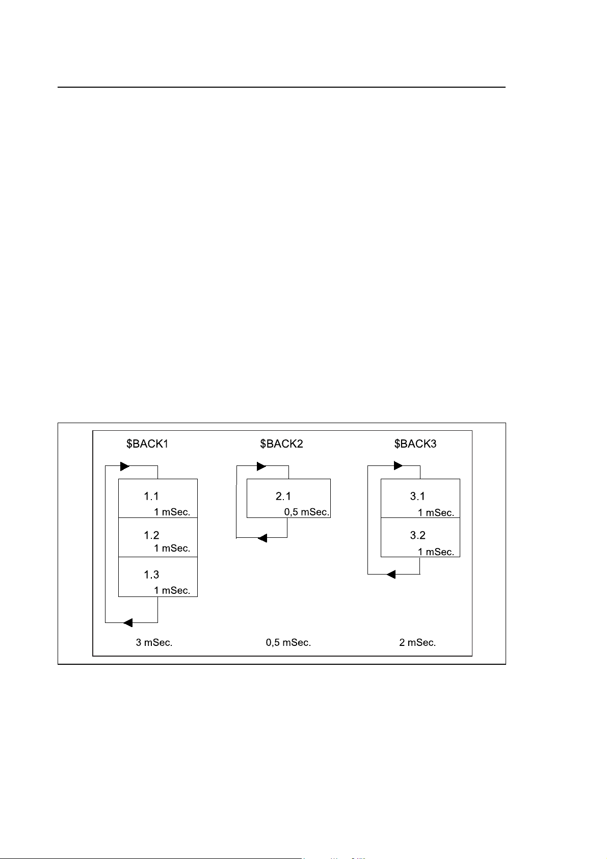
There can be up to 12 background routines. The background routines are those with the lowest priorities among the routines making up the application logic and are executed in turn every 10 ms (WinPlus Tick) for 1 ms. At each WinPlus Tick the integrated PLC updates the I/O's and the foreground routines. Consent routines, part program interfaces and OEM softkeys are enabled at system request and interrupt background execution.
After enabling all high priority routines at each WinPlus Tick, the system enables one of the background routines and lets it run for 1 ms. At each WinPlus Tick the system enables a different background routine. The sequence of activation is determined by the number associated with the routine name. At the first WinPlus Tick the background routine 1 (BACK1) is enabled, at the second the background routine 2 (BACK2) and so on. Once the last background routine has been enabled, the system starts again with the first.
Therefore, an individual background routine is executed over several WinPlus Ticks, alternating part of its code with that of other background routines in time slicing. If a background routine suspends its execution voluntarily by calling a function such as WAIT or DELAY or indirectly by calling system functions of the WAIT type, the remaining time up to the end of the millisecond is available for other system operations (processing a part program, displaying, etc).
If a background routine is shorter than 1 ms, it will execute several times during the WinPlus Tick. If the background task to be enabled is suspended at a new WinPlus Tick, no other background routine is executed and the millisecond reserved for it is used by the system.